High End Munich 2024 - Afterdark x diretta

Singxer SU-6

Voltage

2 items left


Singxer SU-6 
Technical features:

  • SU-6 is a USB digital interface product using XMOS's new xCORE-200 series. The new generation of XMOS chips, using a more advanced process technology, doubled the performance of the old U8 chip, reaching a processing capacity of 1000MIPS.
  • Using high-speed full isolation design, it can very cleanly isolate the interference noise between the computer end and the interface. SU-6 adopts an extraordinary circuit design and uses high-speed PGA to reform the digital audio signal after isolation, so that the signal after the reformation is completely unaffected by the jitter of the isolation chip itself.
  • The SU-6 internal motherboard adopts a unified source synchronous clock technology. The PGA uses a dedicated algorithm to perform strict phase control on the clock signal and digital audio signal, which can ensure that the digital audio signal will not be delayed and phased after passing through the isolation chip. It is poor and there is additional distortion.
  • SU-6 uses an expensive thermostat-level ultra-low jitter clock (femtosecond clock), two CCHD-957 crystal oscillators from Crystek.
  • As we all know, the core of digital audio is the algorithm. The Singxer team has worked in the field of digital audio for many years, and has received strong support from the XMOS AE team. We have made a number of technical improvements and algorithm optimizations based on the original firmware.

Specification:
  • Sampling rate supported by each output interface:
  • PCM: 44.1KHz, 48KHz, 88.2KHz, 96KHz,
  • 176.4KHz, 192KHz, 352.8KHz, 384KHz
  • [I2S out and WCLK out support all sampling rates, S/PDI and AES/EBU support up to 384K, and optical fiber supports up to 192K]
  • DSD: 2.8 MHz (DSD64)-DoP, native
  • 5.6 MHz (DSD128)-DoP, native
  • 11.2 MHz (DSD256)-DoP, native
  • 22.5 MHz (DSD512)-native
[I2S out supports all DSD formats, S/PDI and AES/EBU support DSD128 DOP mode, and optical fiber supports up to DOP64]

Bit width: up to 32 bit over I2S output

Up to 24 bit over S/PDI, AES/EBU

 Specification on Digital Interface:

  • The USB input socket is a standard USB-B type female socket, and the USB power supply range is 4.5V-5.1V;
  • DC POWER input socket adopts DC2.1 socket and supports 7.5V-9V DC input (power supply requirement is 3A).
  • BNC interface and RCA interface output standard S/PDI signal, the level is 550mV (connected to standard load), and the output impedance is 75 ohms;
  • The XLR interface outputs standard AES/EBU signals, the level is 3.3V (connected to standard load), and the output impedance is 110 ohms;
  • The word clock (WCLK) output adopts BNC interface, the level is TTL (without load), and the output impedance is 75 ohms;
  • Two HDMI-I2S signals are output through the HDMI socket. The four output signals include MCLK, BCLK, LRCLK, and SDATA signals, using standard LVDS differential levels, and the impedance is controlled at 100 ohms. Among them, the PIN13-15 of the HDMI socket is the DSD_ON signal. When the level is high, the I2S works in DSD mode, and the level is LVTTL; PIN18 is a 5V weak power output (the output current is less than 20ma), which can be used as an interface plugging indicator; 2 outputs The I2S line sequence is the same.
  • The I2S signal output by RJ45-I2S is a CMOS (5V) single-ended signal, low-impedance output, and the four output signals include MCLK, BCLK, LRCLK, and SDATA signals.
  • The optical fiber port outputs standard optical signals.
 
Digital reclock with external clock 10M:
  1. Carry out the design concept that electricity is the mother of sound, pay attention to the design of power supply circuit, adopt external DC input, built-in super capacitor power supply, and equipped with high-performance, low-noise and fast-response LDO. The whole board uses up to 6 independent LDO power supplies. The digital audio motherboard part is powered by a secondary LDO, and the clock part even uses ADI's ultra-low noise LDO, which lays a solid foundation for ensuring the output performance.
  2. In order to ensure excellent electrical transmission performance, the XLR sockets are made of Swiss Neutrik, the USB-B sockets are made of TE, and the audiophile BNC and RCA coaxial sockets are customized products of major Taiwanese manufacturers. Even the fuses are made from the United States. Litteluse model.
  3. The audio motherboard adopts a 4-layer circuit board design to ensure a complete ground plane and power layer, and a high-speed digital design method to ensure the signal integrity and power integrity of the entire board. The clock signal is specially processed, and the package design and precise impedance control are adopted to ensure the signal quality of the clock and improve its anti-interference ability.
  4. The input and output signals follow the standard design, especially the USB high-speed signal adopts 90 ohm impedance control, and an anti-static TVS protection circuit is built-in; the I2S signal adopts the LVDS differential level standard, the impedance is controlled at 100 ohms, and the 4 outputs are all adopted. A separate LVDS driver.

System compatibility:

  • Windows 7, Windows 8, Windows 10; 32/64 bit, need to install special driver
  • Native MacOS 10.6 and later, use the system's own driver
  • Native Linux with UAC2 compliant kernel, using the system's own driver, (tested on Ubuntu and Daphile systems, based on INTEL X86 platform)


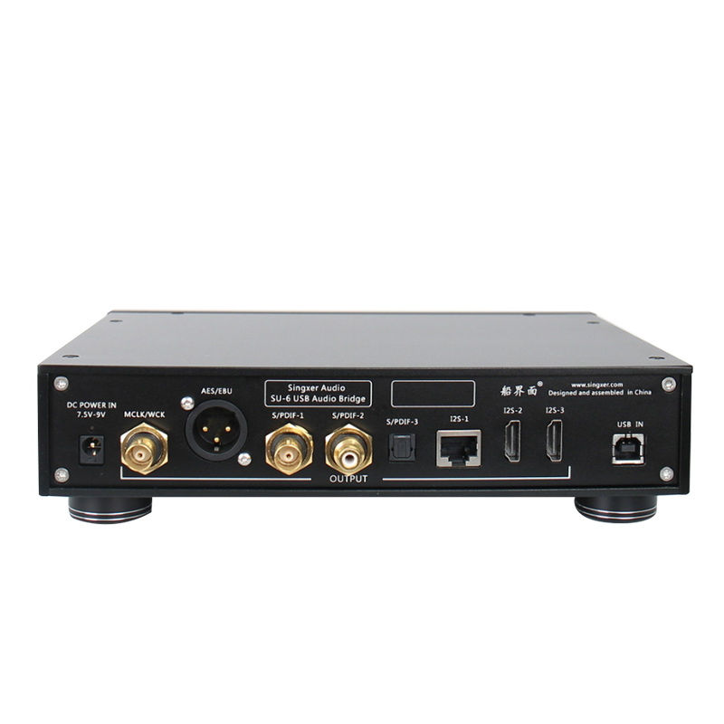
HDMI -I2S interface output:
  1. LVDS differential signal with a level of 3.3V;
  2. DSD ON signal, 5V power supply (small current), MUTE signal internal PGA has been processed, there is no need to output MUTE signal;
  3. The DSD ON signal can be defined by itself, and the DSD ON signal can be output to the PIN13, 14, 15, 16 pins of the socket at will.
  4. The phases of PIN1-3 and PIN7-9 are adjustable, and the user can configure the phases of these two pairs of outputs through a switch.

Flexible I2S and clock configuration:
  • Switches 1-4 correspond to the PIN13-16 pins of the HDMI socket. Pull to the ON position, it means that the PIN pin has the output function of DSD_ON signal;
  • Switches 5 and 6 are the modes for configuring the clock output:
  • When switch 5 is O, the clock outputs MCLK, and when it is ON, the clock outputs WCK;

Switch 6 configures the frequency of MCLK, when it is O, it is 22.5792M/24.576M, when it is ON, it is 45.1584M/49.152M;

The configuration of switch 6 is valid for CLK OUT, RJ45-I2S, and HDMI-I2S.

  1. Switch 7 can independently set the left and right channels in DSD mode in the I2S signal.
  2. Switch 8 can set the line sequence of BCLK in I2S signal; when O, PIN4 is BCLK+, PIN6 is BCLK-;
  3. Switch 9 can set the line sequence of LRCLK in the I2S signal; when O, PIN7 is LRCLK+, PIN9 is LRCLK-;
  4. Switch 10 can set the line sequence of DATA in I2S signal; when O, PIN1 is DATA+, PIN3 is DATA-;
  5. Note: Coaxial, optical fiber, and AES/EBU output are not affected by the above pull switch; the fixed line sequence of RJ45-I2S needs to adapt to different interfaces, and the user needs to customize the network cable.

Diemension and packaging:
  • The length, width and height of the case: 238MM*170MM*46MM, excluding the height of the machine feet and the protruding part of the connector behind the case.
  • The weight of a single machine is about 1.6KG.
  • The length, width and height of the carton packaging: 350MM*230MM*110MM.
  • Packing weight: 2.0KG
  • Accessories: a USB cable, a power adapter (globally, support AC100V-240V), a power cord

所有客戶現在可以通過訪問online shop下訂單,  並通過Visa卡 / Master卡/ PayPal/ Apple Pay/ Goggle Pay 在線直接付款, 接受一切國際訂單。AfterDark網上商店.


Type: DAC


Related Items